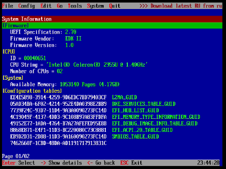
Modifying BIOS Using RU.EFI
This post will describe how to use RU.EFI to modify UEFI Variables in system BIOS. The objective is to enable Intel DCI on a GDP Pocket 2. DCI is Intel’s Ring -2 debugging tool which enables a host to debug the BIOS and operating system of a target machine via a USB cable. There is significant prior art in this area which I would like to credit:
- https://casualhacking.io/blog/2019/6/2/debug-uefi-code-by-single-stepping-your-coffee-lake-s-hardware-cpu
- https://gist.github.com/eiselekd/d235b52a1615c79d3c6b3912731ab9b2
These two articles outline the process of enabling DCI. I will go through the steps of enabling DCI on a GPD Pocket 2 and show a system halt on the host machine of the target CPU. However, this post will focus on using RU.EFI to modify UEFI Variables in BIOS as this is a topic that is not covered in depth in prior art.
Introduction to RU.EFI
RU.EFI is an UEFI Application that can assist in the examination and modification of System BIOS on a running machine. The latest version as of this writing can be found here: http://ruexe.blogspot.com/2020/05/ru-5250379-beta.html. Note that the zip file is encrypted with a password that can only be found in the aforementioned blogpost link.
Since RU.EFI is not open source, I don’t recommend running it on a production machine or a machine with “live” data if you will. I haven’t observed any suspicious behavior, but without having the source code it is very difficult to know if there is any such behavior built in.
You will need to launch RU.EFI from a UEFI Shell. I found the easiest way to boot into an EFI shell is to use a USB stick formatted as FAT. Then create the directory structure /efi/boot/ and copy the UEFI shell binary into the boot directory naming it bootx64.efi. You can find a copy of the EFI shell in the chipsec repo here: https://github.com/chipsec/chipsec/blob/master/chipsec/modules/tools/secureboot/Shell.efi.
You can then copy RU.EFI onto the USB drive. I usually put it in EFI, but it does not matter where it is as long as its on the usb drive. You could even put ru.efi in /efi/boot/bootx64.efi and boot directly into the RU.EFI application, if you so desired.
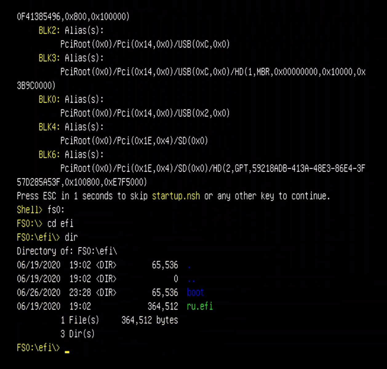
Then if you boot off that same USB drive, you should see the EFI shell. fs0: is the disk you want to jump into. The commands look like this when RU.EFI is in /efi:
fs0:
cd efi
dir
ru.efi
The dir command is optional.
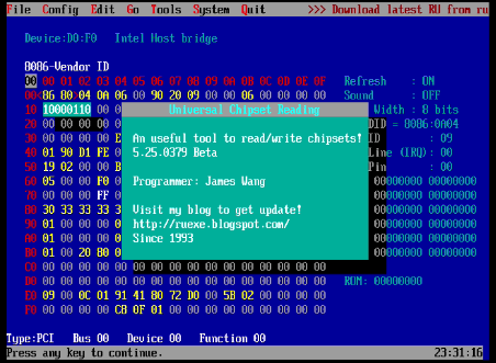
Once you have done that, you will be shown the initial application welcome message:
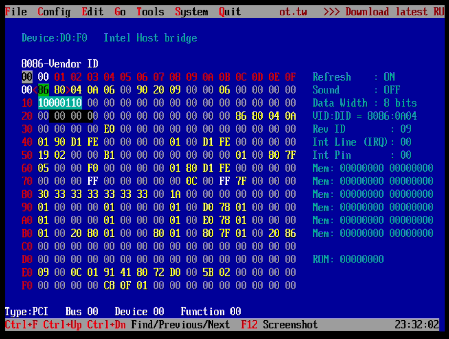
After dismissing the welcom screen you will be presented with the application.
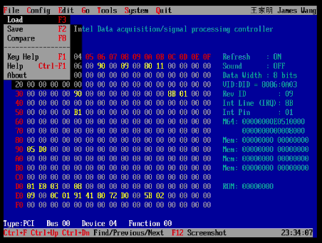
There are seven menus available from the top menu bar:
- File
- Config
- Edit
- tools
- System
- Info
- Quit
File Menu
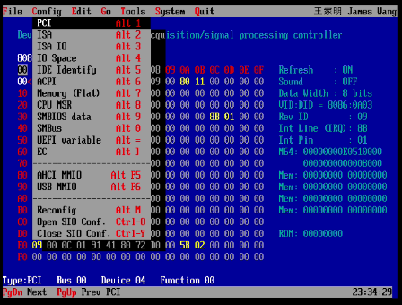
Config Menu
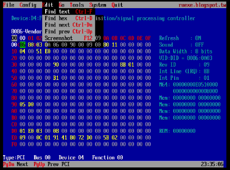
Edit Menu
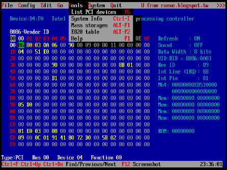
Tools Menu
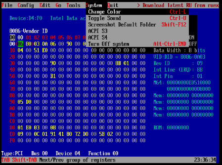
System Menu
Info Menu
And then the last menu, Quit simply exits the application. It can be called at any time with alt+q
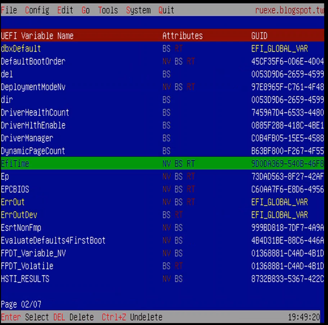
Each menu can be accessed via pressing alt and the underline character key. We will mostly be working with the UEFI Variables Menu, which can be accessed via alt+=.
 ]
]
Prerequistes to Enabling DCI
The first step is to dump the system bios from the target machine. I did this using Chipsec using Linux as the operating system on the target. The chipsec command is chipsec_util spi dump $OUT_FILE_NAME. Chipsec will run on Windows as well, although buidling the kernel driver is a manual process under Windows.
Once I had the BIOS as a binary file, I used UEFITool to extract the Setup UEFI Variable:
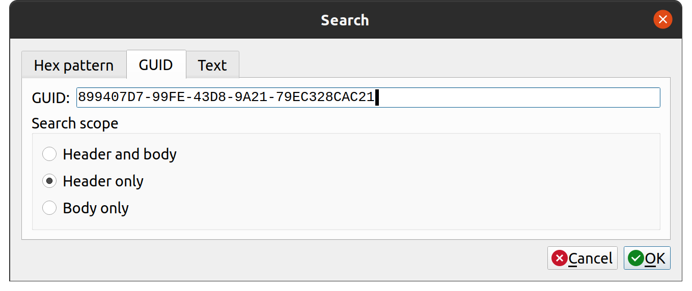
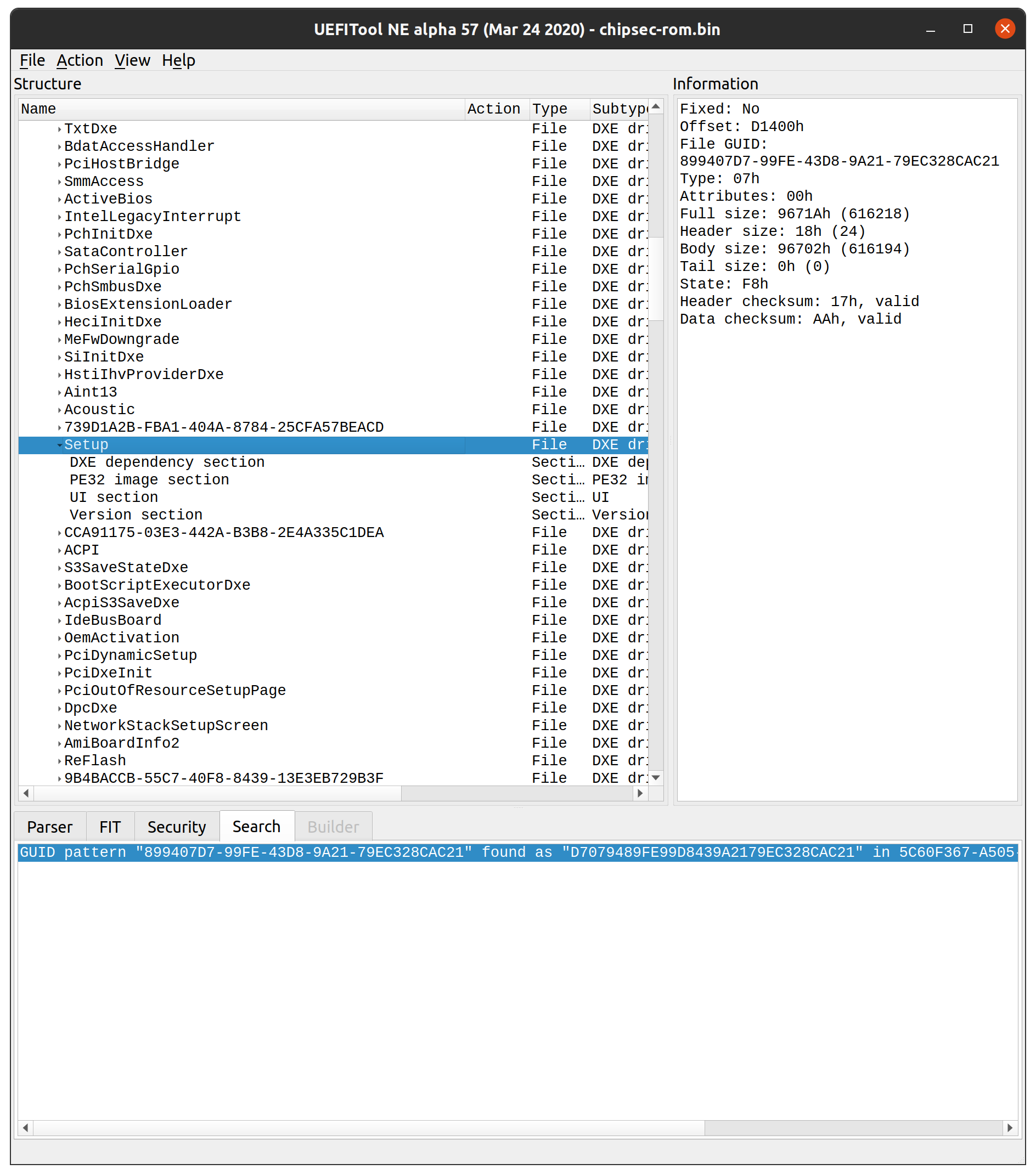
Next we run the Universal IFR Extractor tool on the extracted setup file. Universal IFR Extractor can be downloaded here: https://github.com/LongSoft/Universal-IFR-Extractor.
This tool leaves us with a lot of output we need to sort through. We are looking specifically for UEFI Variables related to DCI or Debugging. The relevant output is posted below:
[...]
0x24970 		Suppress If {0A 82}
0x24972 			QuestionId: 0xC85 equals value 0x0 {12 06 85 0C 00 00}
0x24978 			One Of: Debug Interface , VarStoreInfo (VarOffset/VarName): 0x615, VarStore: 0x1, QuestionId: 0x74, Size: 1, Min: 0x0, Max 0x1, Step: 0x0 {05 91 56 03 57 03 74 00 01 00 15 06 10 10 00 01 00}
0x24989 				One Of Option: Disabled, Value (8 bit): 0x0 (default) {09 07 99 00 30 00 00}
0x24990 				One Of Option: Enabled, Value (8 bit): 0x1 {09 07 98 00 00 00 01}
0x24997 			End One Of {29 02}
0x24999 		End If {29 02}
0x2499B 		Suppress If {0A 82}
0x2499D 			QuestionId: 0xC85 equals value 0x0 {12 06 85 0C 00 00}
0x249A3 			One Of: Debug Interface Lock , VarStoreInfo (VarOffset/VarName): 0x616, VarStore: 0x1, QuestionId: 0x75, Size: 1, Min: 0x0, Max 0x1, Step: 0x0 {05 91 58 03 59 03 75 00 01 00 16 06 10 10 00 01 00}
0x249B4 				One Of Option: Disabled, Value (8 bit): 0x0 {09 07 04 00 00 00 00}
0x249BB 				One Of Option: Enabled, Value (8 bit): 0x1 (default) {09 07 03 00 30 00 01}
0x249C2 			End One Of {29 02}
0x249C4 		End If {29 02}
[...]
0x2DE00 			One Of: Enable/Disable IED (Intel Enhanced Debug), VarStoreInfo (VarOffset/VarName): 0x848, VarStore: 0x1, QuestionId: 0x37A, Size: 1, Min: 0x0, Max 0x1, Step: 0x0 {05 91 8F 07 90 07 7A 03 01 00 48 08 10 10 00 01 00}
0x2DE11 				One Of Option: Enabled, Value (8 bit): 0x1 {09 07 98 00 00 00 01}
0x2DE18 				One Of Option: Disabled, Value (8 bit): 0x0 (default) {09 07 99 00 30 00 00}
0x2DE1F 			End One Of {29 02}
[....]
0x31111 		One Of: DCI enable (HDCIEN), VarStoreInfo (VarOffset/VarName): 0x955, VarStore: 0x1, QuestionId: 0x4DE, Size: 1, Min: 0x0, Max 0x1, Step: 0x0 {05 91 A1 07 A2 07 DE 04 01 00 55 09 10 10 00 01 00}
0x31122 			One Of Option: Disabled, Value (8 bit): 0x0 (default) {09 07 04 00 30 00 00}
0x31129 			One Of Option: Enabled, Value (8 bit): 0x1 {09 07 03 00 00 00 01}
0x31130 		End One Of {29 02}
[...]
0x31BBD 		One Of: xDCI Support, VarStoreInfo (VarOffset/VarName): 0x98B, VarStore: 0x1, QuestionId: 0x523, Size: 1, Min: 0x0, Max 0x1, Step: 0x0 {05 91 1D 0C 1E 0C 23 05 01 00 8B 09 10 10 00 01 00}
0x31BCE 			One Of Option: Disabled, Value (8 bit): 0x0 (default) {09 07 04 00 30 00 00}
0x31BD5 			One Of Option: Enabled, Value (8 bit): 0x1 {09 07 03 00 00 00 01}
0x31BDC 		End One Of {29 02}
[...]
0x31111 		One Of: DCI enable (HDCIEN), VarStoreInfo (VarOffset/VarName): 0x955, VarStore: 0x1, QuestionId: 0x4DE, Size: 1, Min: 0x0, Max 0x1, Step: 0x0 {05 91 A1 07 A2 07 DE 04 01 00 55 09 10 10 00 01 00}
0x31122 			One Of Option: Disabled, Value (8 bit): 0x0 (default) {09 07 04 00 30 00 00}
0x31129 			One Of Option: Enabled, Value (8 bit): 0x1 {09 07 03 00 00 00 01}
0x31130 		End One Of {29 02}
[...]
0x3DEBF 		One Of: TraceHub Enable Mode, VarStoreInfo (VarOffset/VarName): 0xF3B, VarStore: 0x1, QuestionId: 0xA17, Size: 1, Min: 0x0, Max 0x2, Step: 0x0 {05 91 0A 10 0B 10 17 0A 01 00 3B 0F 10 10 00 02 00}
0x3DED0 			One Of Option: Disable, Value (8 bit): 0x0 (default) {09 07 10 10 30 00 00}
0x3DED7 			One Of Option: Host Debugger, Value (8 bit): 0x2 {09 07 11 10 00 00 02}
0x3DEDE 		End One Of {29 02}
From this we can come up with a list of Setup variable offsets that need to be changed:
- 0x615: 0 to 1
- 0x616: 1 to 0
- 0x848: 1 to 0
- 0x955: 1 to 0
- 0x4DE: 1 to 0
- 0xF3B: 0 to 2
We now use RU.EFI’s hex editor to modify bytes in the Setup variable:
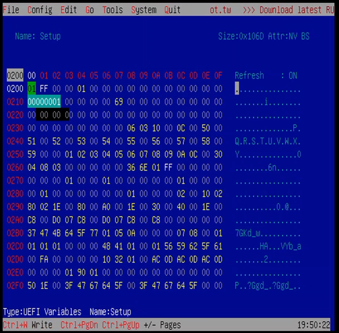
Changes are made by using the arrow keys to select the appropriate offset and then entering the hex value and pressing enter. To write the value back to BIOS, press crtl+w. Make all of the aforementioned offset changes, write the values to BIOS, and then exit the application and run reset at the UEFI shell.
Testing DCI
Next we plug in our target machine to our host machine using a USB3.0 cross over cable. This is a USB-A to USB-A cable.
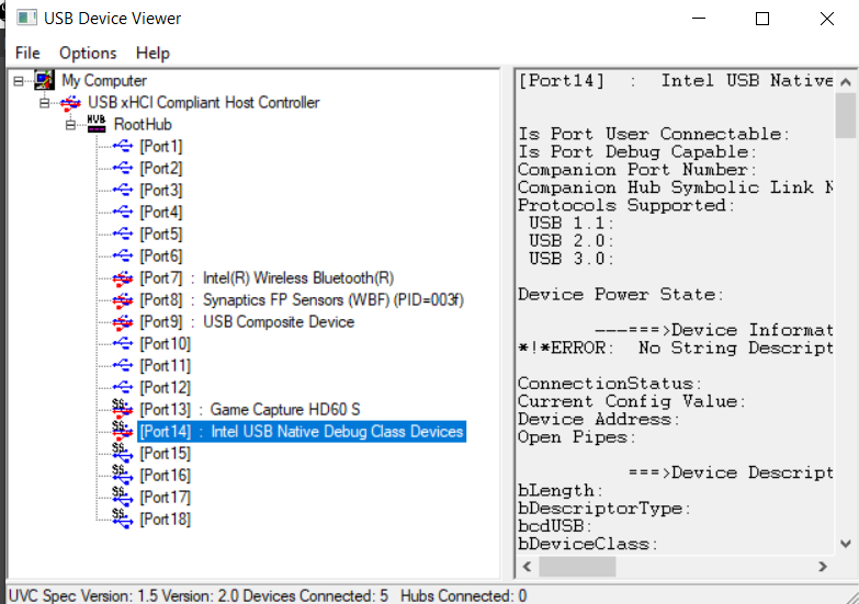
If we check the USB Tree View, the Target should appear like this:
We need Intel System Studio installed on our host machine. Intel System Studio can be downloaded here: https://software.intel.com/content/www/us/en/develop/tools/system-studio/choose-download.html. Also worth noting is that on the GPD Pocket 2, only the right USB-A port seemed to work with DCI.
For whatever reason, I was not able to get a debug connection established using the Intel System Studio Debugging tools, so I had to use the Legacy Debugger which is available as part of the Intel System Studio 2020 installation. The Legacy Debugger can be launched by running C:\Program Files (x86)\IntelSWTools\sw_dev_tools\system_debugger_2020\system_debug_legacy\xdb.bat.
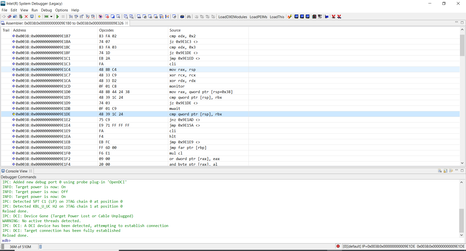
Interrupting the CPU results in a processor halt on the target and control transfered to the host!
