TempleOS Reverse Engineering
Introduction
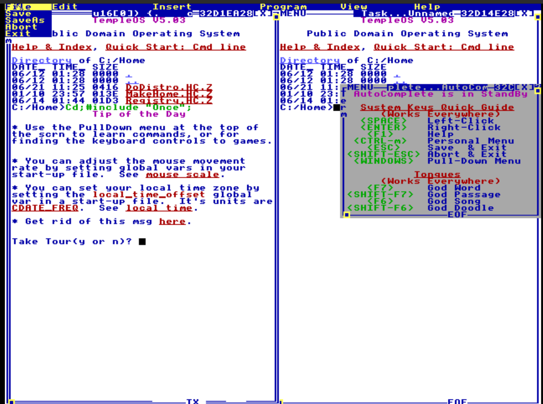
TempleOS (https://www.templeos.org/) is an operating system written by Terry A Davis. Terry suffered from a severe mental illness that eventually claimed him, but he also produced this very interesting piece of software without the source code. TempleOS is part of the public domain, and I wanted to take a look at it to come to an understanding of how it works to honor Terry’s struggle.
A side note: millions of people every year suffer from severe mental illness. You can make an impact by donating to a cause such as NAMI, or other such organizations in your part of the world.
Terry presented some of the source code online here: https://github.com/cia-foundation/TempleOS. Note the repository does not include source code for the kernel, bootloader, or boot sector.
You can read more about Terry and the history of TempleOS on Wikipedia

Reversing TempleOS
Let’s start from the beginning.
After downloading the TempleOS ISO installer, I created a Virtual Machine with a 1GB virtual hard disk. I then connected the TempleOS ISO file as a virtual cdrom drive and booted the virtual machine. The VM then booted up and I went through the installation process of installing TempleOS onto a QEMU qcow2 virtual hard disk file. After the installation was complete, I shutdown the virtual machine.
Next, I connected the qcow2 virtual hard disk file using qemu-nbd. Instructions on how to connect a qcow2 file in Linux can be found here.
I then looked at the fdisk output for the mounted image:
Disk /dev/nbd0: 1 GiB, 1073741824 bytes, 2097152 sectors
Units: sectors of 1 * 512 = 512 bytes
Sector size (logical/physical): 512 bytes / 512 bytes
I/O size (minimum/optimal): 512 bytes / 512 bytes
Disklabel type: dos
Disk identifier: 0x040dcbcf

Device      Boot   Start     End Sectors   Size Id Type
/dev/nbd0p1 *         63 1060289 1060227 517.7M  b W95 FAT32
/dev/nbd0p2 *    1060353 2088449 1028097   502M  b W95 FAT32
I saw there are two partitions on the virtual hard disk, both of which are FAT32. I knew the first partition contained the bootsector, so I decided to look at the second partition to begin with. I mount the second partition and copied off all the files from the mount point to my research directory for further analysis.
Filesystem
The FAT32 filesystem in the second partition contained a bunch of files for normal OS operation. The list of files can be found here.
The first directory on the filesystem is 0000Boot which contains one file: 0000Kernel.BIN.C. This is what one might describe in modern terms as a bootloader along the lines of GRUB2/Winload. It does not adhere to any standardized binary file format such as ELF, PE32, Mach-O or even COFF. I tried to load this file alone into Ghidra and could not figure out the load address for the life of me, even when attempting to bruteforce the load address. I put the project aside for a few days while I thought about what to do next.
Boot Sector
Eventually I realized that I was going to need to analyze the TempleOS bootsector. This is the first 512 bytes of the first partition. I carved out those bytes and took a look:
00000000: eb58 904d 5357 494e 342e 3100 0202 2000  .X.MSWIN4.1... .
00000010: 0200 0000 00f8 0000 0000 0000 0000 0000  ................
00000020: 832d 1000 2e10 0000 0000 0000 0200 0000  .-..............
00000030: 0100 0000 0000 0000 0000 0000 0000 0000  ................
00000040: 8001 2923 1032 b14e 4f20 4e41 4d45 2020  ..)#.2.NO NAME
00000050: 2020 4641 5433 3220 2020 fcb8 c096 668e    FAT32   ....f.
00000060: c0fa 668e d0bc 0004 fbe8 0000 5b83 eb6c  ..f.........[..l
00000070: c1eb 0466 8cc8 03c3 668e d8b9 0002 33f6  ...f....f.....3.
00000080: 33ff f3a4 b8c0 9666 8ed8 eaa2 00c0 9600  3......f........
00000090: 7301 1000 0100 0000 0000 51a9 0000 0000  s.........Q.....
000000a0: 0000 6788 158f 0000 00b8 c007 668e c066  ..g.........f..f
000000b0: 33c9 678b 0d90 0000 0051 0666 8cc0 a398  3.g......Q.f....
000000c0: 00be 9200 b442 678a 158f 0000 00cd 1358  .....Bg........X
000000d0: 0520 0066 8ec0 6667 ff05 9a00 0000 7508  . .f..fg......u.
000000e0: 6667 ff05 9e00 0000 59e2 ce66 33db 66b8  fg......Y..f3.f.
000000f0: 0300 0000 ea00 00c0 0700 0000 0000 0000  ................
00000100: 0000 0000 0000 0000 0000 0000 0000 0000  ................
00000110: 0000 0000 0000 0000 0000 0000 0000 0000  ................
00000120: 0000 0000 0000 0000 0000 0000 0000 0000  ................
00000130: 0000 0000 0000 0000 0000 0000 0000 0000  ................
00000140: 0000 0000 0000 0000 0000 0000 0000 0000  ................
00000150: 0000 0000 0000 0000 0000 0000 0000 0000  ................
00000160: 0000 0000 0000 0000 0000 0000 0000 0000  ................
00000170: 0000 0000 0000 0000 0000 0000 0000 0000  ................
00000180: 0000 0000 0000 0000 0000 0000 0000 0000  ................
00000190: 0000 0000 0000 0000 0000 0000 0000 0000  ................
000001a0: 0000 0000 0000 0000 0000 0000 0000 0000  ................
000001b0: 0000 0000 0000 0000 0000 0000 0000 0000  ................
000001c0: 0000 0000 0000 0000 0000 0000 0000 0000  ................
000001d0: 0000 0000 0000 0000 0000 0000 0000 0000  ................
000001e0: 0000 0000 0000 0000 0000 0000 0000 0000  ................
000001f0: 0000 0000 0000 0000 0000 0000 0000 55aa  ..............U.
This looks like a boot sector! I threw this into Ghidra in x86 16bit Real mode with a load address of 0000:7c00 which is where the BIOS expects the boot sector to be and where the BIOS hands off execution to the operating system at.

The first instruction looks like this:
//
// ram
// ram:0000:7c00-ram:0000:7dff
//

assume DF = 0x0  (Default)
0000:7c00 eb 58           JMP        LAB_0000_7c5a
As we can see, this instruction jumps to address 0000:7c5a:

LAB_0000_7c5a                                   XREF[1]:     0000:7c00(j)
0000:7c5a fc              CLD
0000:7c5b b8 c0 96        MOV        AX,0x96c0
0000:7c5e 66 8e c0        MOV        ES,AX
0000:7c61 fa              CLI
0000:7c62 66 8e d0        MOV        SS,AX
0000:7c65 bc 00 04        MOV        SP,0x400
0000:7c68 fb              STI
0000:7c69 e8 00 00        CALL       LAB_0000_7c6c
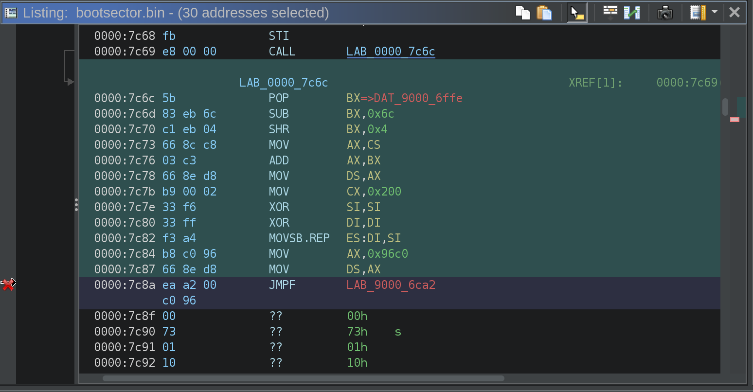
This is where the stack is set up. At the end the CALL instruction transfers control of execution to LAB_0000_7c6c.

LAB_0000_7c6c                                   XREF[1]:     0000:7c69(j)
0000:7c6c 5b              POP        BX=>DAT_9000_6ffe
0000:7c6d 83 eb 6c        SUB        BX,0x6c
0000:7c70 c1 eb 04        SHR        BX,0x4
0000:7c73 66 8c c8        MOV        AX,CS
0000:7c76 03 c3           ADD        AX,BX
0000:7c78 66 8e d8        MOV        DS,AX
0000:7c7b b9 00 02        MOV        CX,0x200
0000:7c7e 33 f6           XOR        SI,SI
0000:7c80 33 ff           XOR        DI,DI
0000:7c82 f3 a4           MOVSB.REP  ES:DI,SI
0000:7c84 b8 c0 96        MOV        AX,0x96c0
0000:7c87 66 8e d8        MOV        DS,AX
0000:7c8a ea a2 00 c0 96  JMPF       LAB_9000_6ca2
This is where things get interesting. The end of this code is a far jump to LAB_9000_6ca2, which is not contained in the bootsector. It looks like 96c0 is moved into AX and then from AX into DS before the far jump. Since x86 Real Mode uses 20-bit addressing, the far jump ends up handing control of execution somewhere inside of 0000Boot/0000Kernel.BIN.C. piecing together the data segment register value and the far jump, I figured out that the load address for 0000Boot/0000Kernel.BIN.C is 9000:6c00. I load 0000Kernel.BIN.C into Ghidra, once again in x86 Real Mode and set the load address to 9000:6c00, and ghidra was able to make some sense of the 0000Kernel.BIN.C file now!
0000Kernel.BIN.C

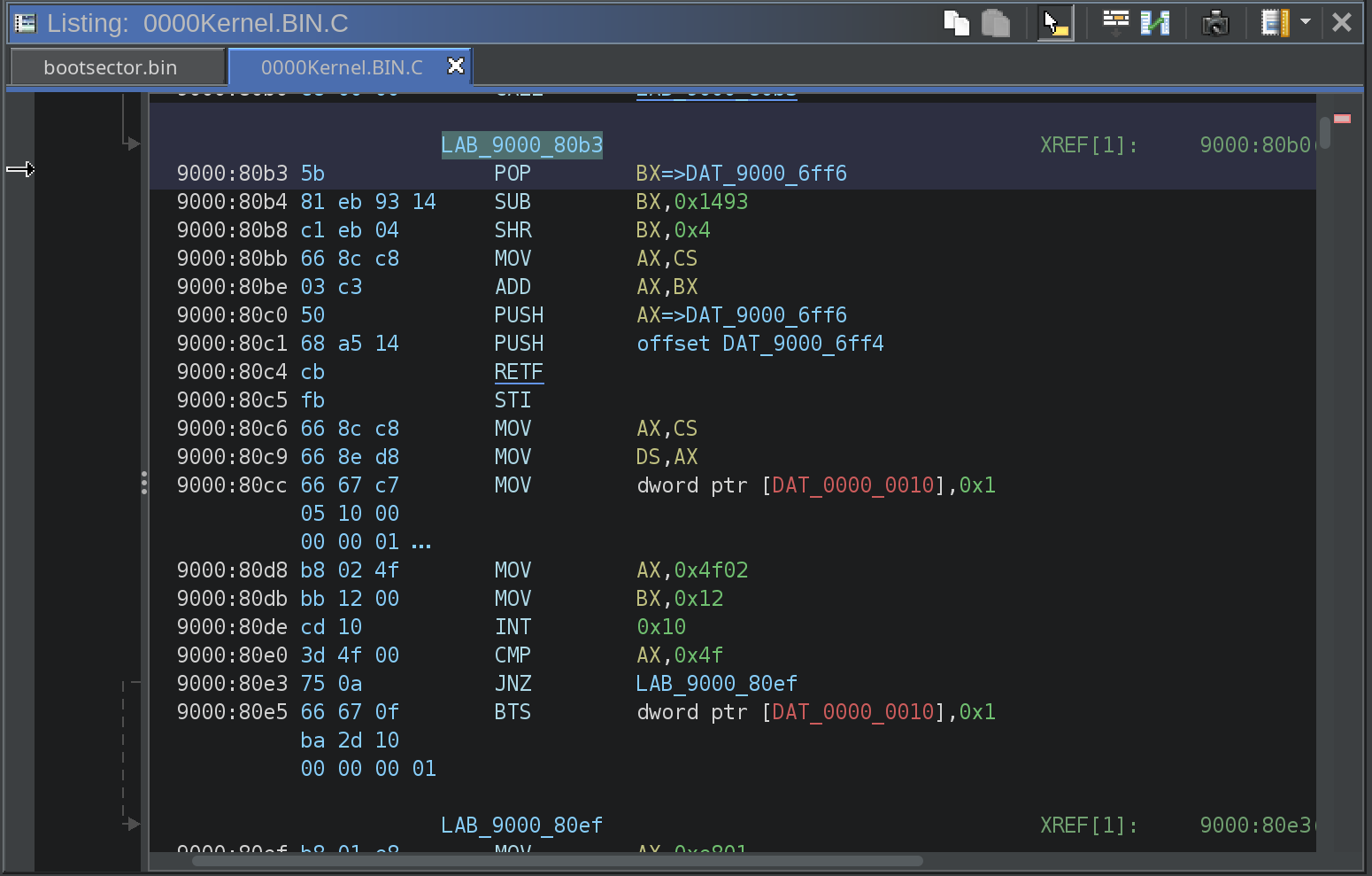
The first instruction inside the 0000Kernel.BIN.C file is a jump just like the bootsector, and then there are a few more jumps and minor instructions until execution reaches LAB_9000_80b3.

LAB_9000_80b3                                   XREF[1]:     9000:80b0(j)
    9000:80b3 5b              POP        BX=>DAT_9000_6ff6
    9000:80b4 81 eb 93 14     SUB        BX,0x1493
    9000:80b8 c1 eb 04        SHR        BX,0x4
    9000:80bb 66 8c c8        MOV        AX,CS
    9000:80be 03 c3           ADD        AX,BX
    9000:80c0 50              PUSH       AX=>DAT_9000_6ff6
    9000:80c1 68 a5 14        PUSH       offset DAT_9000_6ff4
    9000:80c4 cb              RETF
    9000:80c5 fb              STI
    9000:80c6 66 8c c8        MOV        AX,CS
    9000:80c9 66 8e d8        MOV        DS,AX
    9000:80cc 66 67 c7        MOV        dword ptr [DAT_0000_0010],0x1
              05 10 00
              00 00 01
    9000:80d8 b8 02 4f        MOV        AX,0x4f02
    9000:80db bb 12 00        MOV        BX,0x12
    9000:80de cd 10           INT        0x10
    9000:80e0 3d 4f 00        CMP        AX,0x4f
    9000:80e3 75 0a           JNZ        LAB_9000_80ef
    9000:80e5 66 67 0f        BTS        dword ptr [DAT_0000_0010],0x1
              ba 2d 10
              00 00 00 01
The interesting thing here is that the second stage bootloader (0000Kernel.BIN.C) references pointers to the bootsector. That is not something I have seen anywhere else.
Analysis
The boot sequence up to this point looks completely different than any other primary/secondary bootloader I’ve ever looked at. It demonstrates a lot of creativity in the writing process, but I admit I’m not sure what was behind some of the design decisions. Usually, as a reverse engineer, I can understand what the original developer was trying to do, but this boot sequence is really something else. Additionally, there are no ASCII or UNICODE strings in 0000Boot/0000Kernel.BIN.C, making the reverse engineering process pretty tedious.
My next step is going to be figuring out where 0000Kernel.BIN.C transfers execution to. I’m pretty sure its going to be Kernel.BIN.C, but I will need to keep digging to figure out where Kernel.BIN.C is loaded into memory. 0000Kernel.BIN.C should give me the answer to that question after some more research. I’m also curious where the transition out of Real Mode happens; whether is in 0000Kernel.BIN.C or Kernel.BIN.C. My guess is the later, but it will be fun to figure out. Look for another post in this series soon!